SWF series chip-level substrate integrated waveguide (SIW) filter is manufactured on DWMicrowave’s semiconductor process with silicon substrate. It offers two assemble configurations: bare die for wire-bonding /ribbon-bonding and chip size package for surface mount (SMD) using reflow soldering.
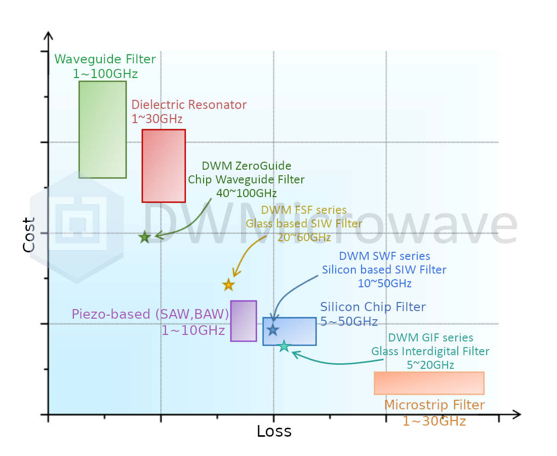
DWMicrowave currently offers four filter product series designed for different frequency bands and performance requirements. Among these, the ZeroGuide series is currently under development, while the rest are already in mass production. Their microwave performance and cost are detailed in the figure below.
As shown in the figure above, the SWF-series filters are suitable for applications ranging from 10 GHz to 50 GHz, featuring low insertion loss and low temperature drift.
Customized semiconductor process flow
Manufactured on semiconductor process, very high microwave performance consistency. Filters can be customized to meet specific user requirements
Excellent PIM performance
By replacing the nickel with non-magnetic metal, The DWMicrowave’s SWF series filters provide outstanding PIM performance, which is close to the waveguide filters.
Suitable for airtight and vacuum environments
The DWMicrowave’s wire-bonding SWF series filters, manufactured by specialized semiconductor process, are free from organic polymers, completely avoiding the out-gassing issues and are especially suitable for airtight or vacuum applications.
Very low temperature drift
SWF series filter offers very low temperature drift. The table below provides the temperature coefficient of frequency (TCF) of the 21-23GHz SWF series filters.
Part Ordering Guide
Below are the basic parameters of the SWF22B1P4N5 filter. For the more detailed datasheet and S-parameter files, please contact us.
SWF22B1P4N5
Electrical Specifications
Data is measured with 2 wirebonds with approximately 25μm diameter, 50μm height, on the DWMicrowave test board. Test board is connected to VNA with 2.4mm connectors. The connector and coaxial cables are deembedded.
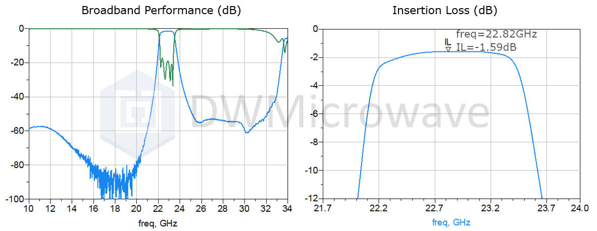
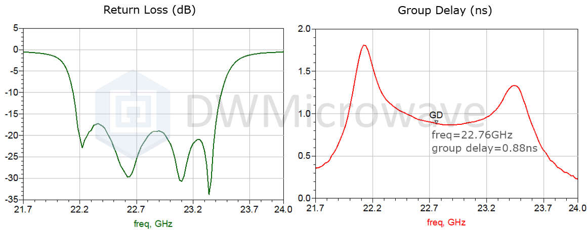
Typical Performance
Mechanical Drawing
In the top view above, the shaded areas are for wire-bonding. Outline dimensions are given below, unit is millimeter.
For datasheets and S2P files of other chip models, please also contact us.